You are an L1 router
If you are reading this chances are you’re familiar with what IS-IS is and how it works. I don’t know about you but I’ve always wondered about the exact meaning of the Attributes section in the isis database output of Junos devices. Let’s take a look.
ruissalo@r1_re0> show isis database
IS-IS level 1 link-state database:
  0 LSPs

IS-IS level 2 link-state database:
LSP ID                      Sequence Checksum Lifetime Attributes
R1_re0.00-00           0x1ca5d   0x5ba9     1051 L1 L2
R2_re0.00-00            0xf91a   0x65fa      611 L1 L2
R3_re0.00-00           0x11e1f   0x2da6     1187 L1 L2
R9_re0.00-00           0x23fb7   0xac86     1079 L1 L2
(...)
According to the level 1 section output, we could assume this particular level was disabled on the device because no router is currently injecting LSPs into this topology, at least from R1’s perspective. This theory can be easily confirmed by looking at the configuration:
ruissalo@r1_re0> show configuration protocols isis | display set | display inheritance no-comments
set protocols isis level 2 wide-metrics-only
set protocols isis level 1 disable
(...)
As we expected level 1 has been disabled making this an L2 only router; this same config knob can also be found on R2, R3 and R9. - Many engineers choose to run L2 only deployments to eliminate chances of default routes installed towards L2L1 routers with the Attached bit set - So if this is an L2 only device, why is it that the output shows the L1 and L2 flags on each of the LSPs? Entry details also show the same.
ruissalo@r1_re0> show isis database r1_re0.00-00 extensive | match Attributes
    Checksum: 0xad86, Sequence: 0x5fed4, Attributes: 0x3 <L1 L2>
Where is this information coming from anyway?
The Attribute block is nothing more than the last octet on both L1 and L2 link-state PDUs - packet types 18 and 20. It’s worth noting that the IS-IS decision process will consider this octet only when it’s present in the first fragment (in case multiple fragments were needed to achieve full synchronization)
The diagram below shows the PDU header composed of the ISIS common header followed by the Lifetime, LSP ID and Sequence Number, all three values displayed in the router’s isis database output we saw before.
                                       No. of Octets

   ----------------------------------
  |      Common Fixed Header        |     8
   ----------------------------------
   ----------------------------------
  |          PDU Length             |     2
   ----------------------------------
  |      Remaining Lifetime	        |     2
   ----------------------------------
  |           LSP ID                |  ID Length + 2
   ----------------------------------
  |      Sequence Number            |     4
   ----------------------------------
  |           Checksum              |     2
   ----------------------------------
  |  P | ATT | LSPDBOL | *IS Type*  |     1
   ----------------------------------
   ----------------------------------
  |             TLVs                |    Variable
  -----------------------------------
To understand the exact meaning of the information conveyed by the last octet let’s see what ISO 10589, available here, has to say about that:
P - Bit 8 when set, indicates support for Partition repair. This is an optional functionality, meaning neither Juniper nor Cisco implements it :)
ATT - Bits 7-4 indicate, when set, the issuing Intermediate System is “attached” to other areas. Why 4 bits? in the 1980s designers thought it was a good idea to support multiple topologies based on different metrics like delay, expense and error. Because complexity is never a good thing, this multidimensional approach wasn’t adopted and use of bits 5,6 and 7 is deprecated today.
LSPDBOL - Bit 3 is used to ‘overload’ the database.
And finally we get to meet the IS Type bits. As it turns out these 2 bits indicate the type of Intermediate System that generated the LSP1! And this is the source of the information shown in the Attributes Block on the isis database output we saw previously. According to ISO 10589 allowed values are as follow:
- 0 - Unused value
- 1 - bit 1 set means Level 1 Intermediate System
- 2 - Unused value
- 3 - bits 1 and 2 set, Level 2 Intermediate System
Remember in IS-IS we can have three types of routers: L1 only, L2 only and L1-L2, but with only 2 values to choose from (1 or 3 - bit 1 must always be set) there is no way to make the difference between an L2 only system and an L1L2 system by looking at the Attributes block from an L2 LSP PDU. So while L1L2 routers will designate a System as “IS Type” 3 on both type 18 and type 20 LSP PDUs, L2 only routers will do the same when generating type 20 PDUs.
To make things even more confusing, we saw how Juniper’s database uses the ‘L1L2’ output to designate IS Type 3 LSPs entries. Now, let’s see what our dear friend Wireshark is telling us.
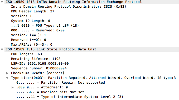
The image shows a type 20 PDU (L2 LSP) from an L1L2 adjacency between two devices, note how Wireshark decodes IS Type 3 with a “Level 2” string.
Why IS-IS protocol designers made this decision seems to be related to how CLNP worked at that time: There was no such a thing as an L2-only router in the early days of the protocol - this restriction relaxed later for IP.
In any case, always remember to check the actual content of the database, or simply the adjancency list, before arriving to any conclusions about the IGP topology: don’t be fooled by the LSPs Attributes block.
-
A system’s IS Type also plays an interesting role when an router is determining the adjacency usage type. You can read more about this in section 8.4.3.2 of ISO 10589. ↩